


INTRODUCTION
Transforaminal lumbar interbody fusion (TLIF) is commonly used to treat a variety of symptomatic lumbar pathology. The procedure involves discectomy followed by placement of an implant into the intervertebral space [1,2]. This technique provides spinal arthrodesis, maintenance of disc height, and preservation/correction of spinal alignment [3].
Developments in spinal instrumentation and radiological imaging have now made minimally invasive surgery (MIS) possible. In 2002, this procedure was performed with tubular retractors for sequential muscle dilation to reduce soft tissue trauma [4]. Additionally, radiological guidance was used to facilitate placement of the interbody device and the percutaneous rod-screw system [4]. The effectiveness of the MIS TLIF has been previously demonstrated to be associated with improved postoperative outcomes such as reduced blood loss, smaller incision size, shorter hospitalization, and less pain [5-8]. Disadvantages and limitations of the MIS TLIF include the learning curve that must be surmounted before achieving technical proficiency and the technical demands of a smaller working area. When combined with a bulky retractor system, this can limit the surgeon’s ability to visualize, distract, or alter the patient’s anatomy to achieve the desired outcome.
The Space-D Access System (Medtronic, Minneapolis, MN, USA) is a new, multifunctional, minimally invasive system that allows for tissue retraction and pedicle-to-pedicle distraction or compression. The use of this system enables surgeons to efficiently and safely perform a MIS TLIF. Unlike tubular access systems which can migrate in soft tissue, the Space-D Access System is fixated to the pedicle screws, providing the surgeon with a continuous reference point for anatomical landmarks and boundaries. Additionally, the ability to distract between pedicles enhances the view of the surgical field and expands the surgical corridor for placement of a larger interbody device, if necessary. This device is compatible with placement of pedicle screws and interbody cages with 3-dimensional (3D) intraoperative navigation using the StealthStation (Medtronic).
METHODS
Space-D, StealthStation, CD Horizon Solera Voyager (Medtronic), and an anatomic lumbar spine model were used to demonstrate the steps to successfully perform a MIS TLIF with this novel system. Screenshots obtained from the StealthStation were taken from a deidentified patient to demonstrate the use of intraoperative navigation.
PROCEDURAL TECHNIQUE
1. Preoperative Planning
An approach from either side still can achieve adequate central and contralateral decompression; however, MIS TLIF is preferentially performed on the more symptomatic side. Plain films, magnetic resonance imaging and/or computed tomography (CT) of the spine are examined for anatomical variants, including disc herniations, facet hypertrophy, and pars fractures. Lumbar pedicle size can be assessed preoperatively to determine the appropriate length and diameter of pedicle screws. In the setting of deformity correction, standing upright scoliosis films can also be obtained to determine spinal alignment parameters. Dual-energy x-ray absorptiometry is not commonly performed on asymptomatic patients who will undergo procedures using the Space-D Access System, but can be performed when there is concern for osteoporosis. The above findings help guide the surgeon to select the appropriate levels and type of interbody cage(s). As with any other procedure, the risks, benefits and alternatives should be discussed at length with the patient prior to surgery.
2. Patient Positioning
General anesthesia is induced, and the patient is positioned prone using a Jackson table with chest, hip, and thigh pads. The hips are placed in a neutral position to maximize lumbar lordosis. The patient is placed in a slight reverse Trendelenburg position so that the orbits are above the chest to prevent facial venous congestion and decrease the risk of iatrogenic blindness [9,10]. Bony prominences are carefully padded, and the patient is secured to the table using a safety belt. The operative site is then prepped and draped in the standard sterile fashion.
3. Navigation Equipment and Room Setup
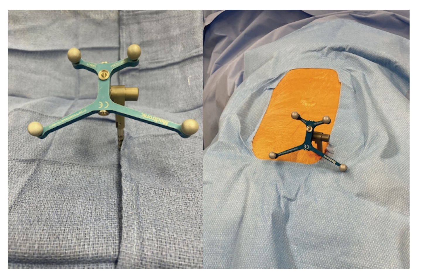
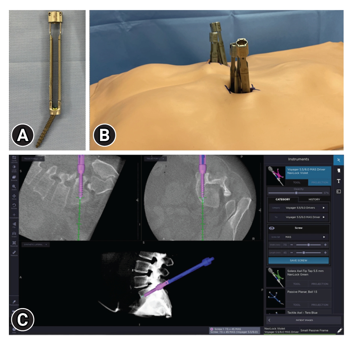
Within the StealthStation instrument panel, the navigated probe and driver are selected. This informs the software of the intended instruments to be used during the procedure and allows the camera to recognize the devices when placed in view. To establish a point of anatomical reference, a percutaneous pin with a reference frame is then placed in the posterior superior iliac spine (PSIS) (Figure 1). Alternatively, a small midline incision can be made to attach a spinous process clamp with a reference frame. A sterile drape is placed over the patient, and the O-arm (Medtronic) is brought into the surgical field and connected to the StealthStation to acquire a 3D CT that displays real-time position of navigated instruments throughout the case. The O-arm and drape are then removed. The remainder of the procedure is carried out with surgical loupes or microscope and long bayonetted instruments. Neuromonitoring is routinely employed, specifically with triggered electromyography (EMG) of pedicle tap and screw to assess for malposition.
4. Insertion of Pedicle Screws
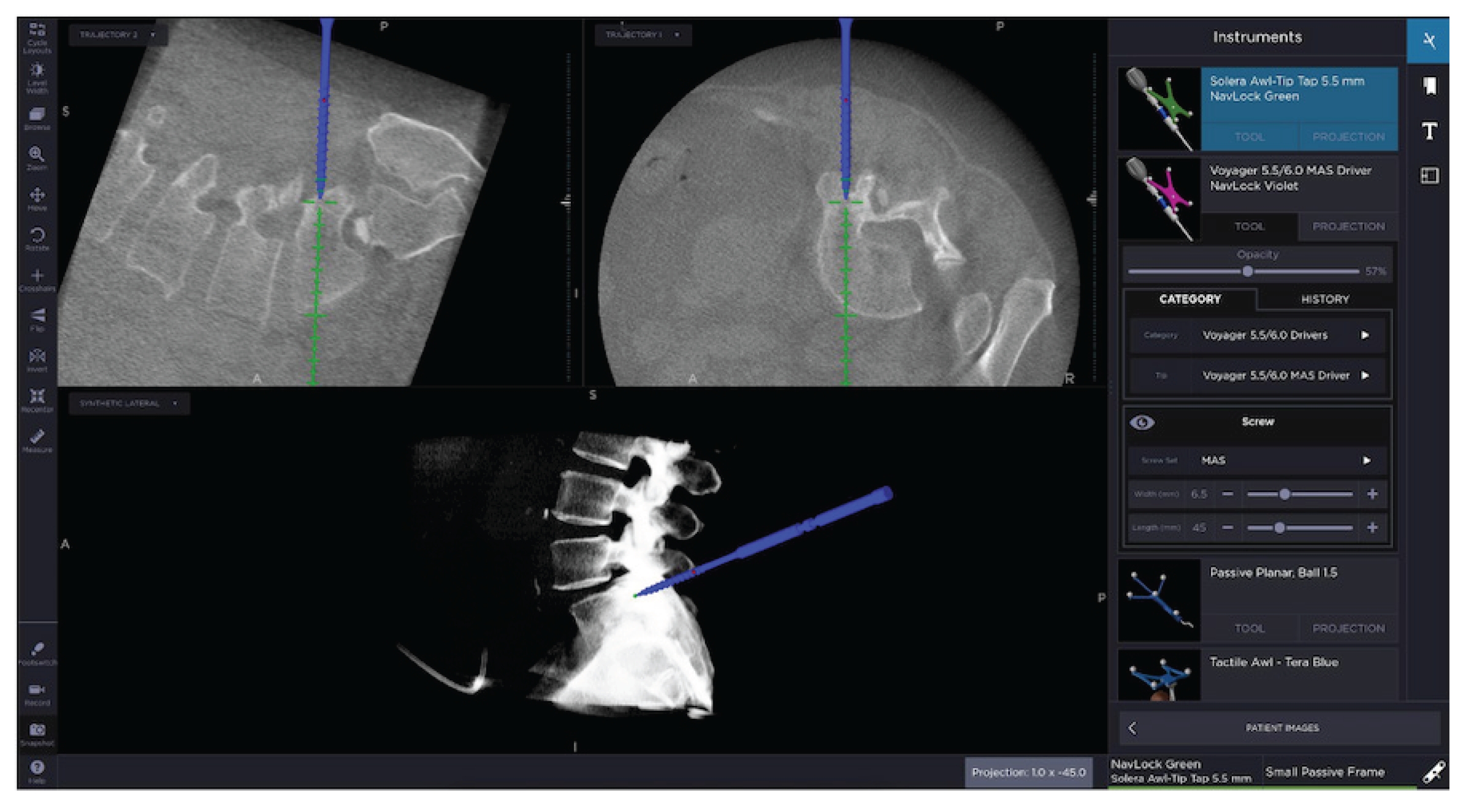
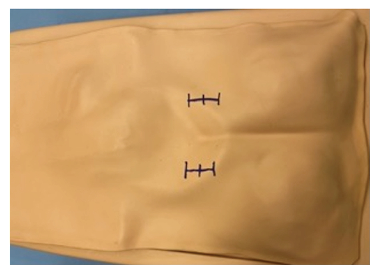
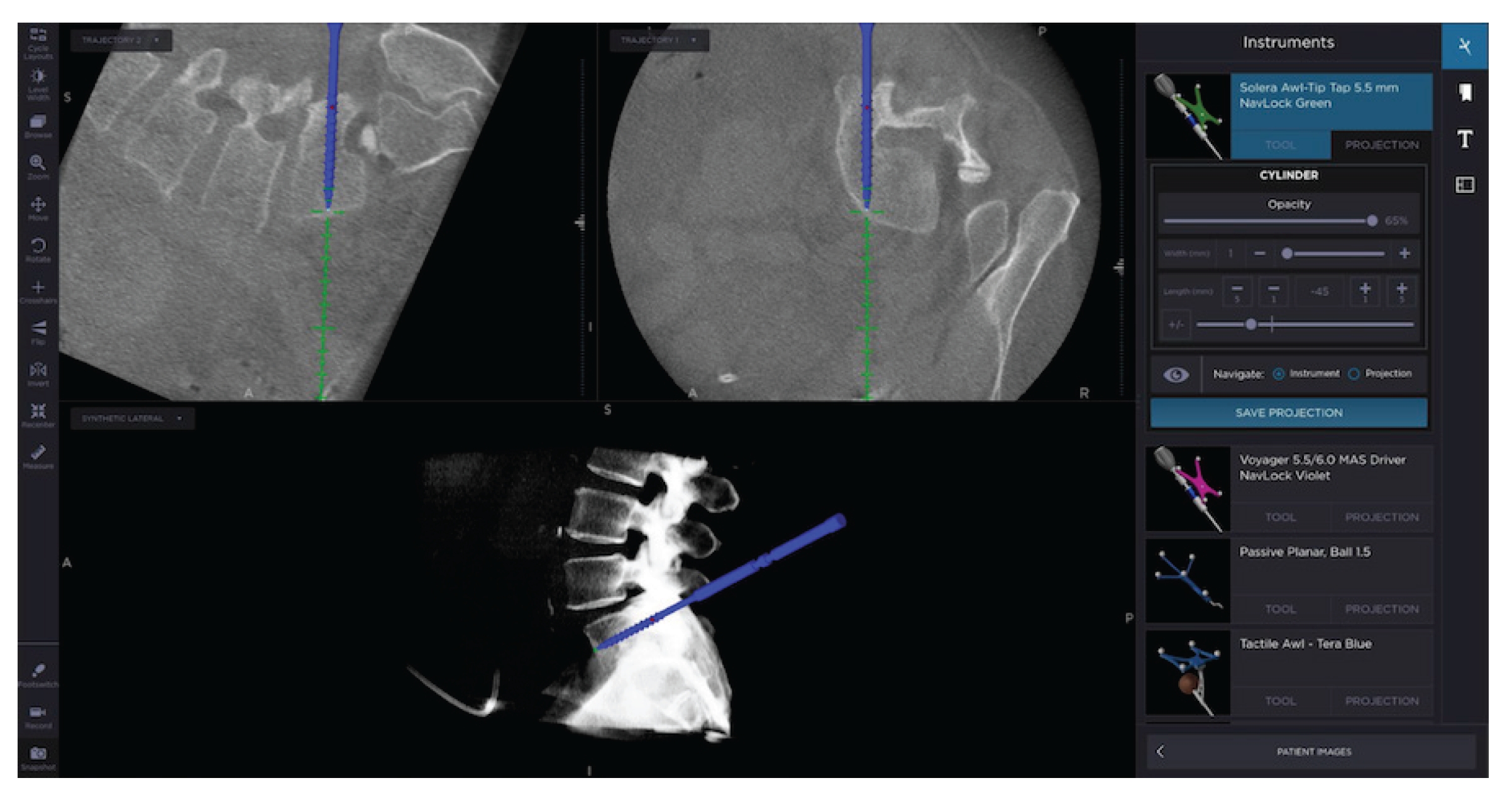
The screw trajectory is planned from the skin surface with the StealthStation and navigated probe (Figure 2). Bilateral Wiltse incisions are made through the skin where the screw trajectory projections intersect the skin (Figure 3). Electrocautery is used to dissect the subcutaneous tissue and incise the fascia. Bipolar coagulation is used to achieve hemostasis. Using 3D navigation, the pedicle is cannulized to the desired depth with a navigated tap (Figure 4). The projection is saved and provides a guide for pedicle screw placement. Prior to removal of the tap, stimulation with triggered EMG is performed to assess for breach of the pedicle wall. Commonly, a stimulation of ≥6 mA without eliciting a muscle response is used as a threshold to confirm adequate placement at our institution. Next, the CD Horizon Solera Voyager extenders and cap are assembled onto the top of the screw and inserted under image-guidance along the previously saved trajectory (Figure 5). The screw-extender assembly should not be advanced so far that the screw loses its polyaxial capabilities. Triggered EMG is performed again after screw placement with a 6-mA threshold. These steps are repeated until all screw have been inserted into the desired levels. Alternatively, pedicle screws can be placed with multiplanar fluoroscopy and Kirschner wires. Once completed, ensure there is a single fascial incision between each pedicle screw extender. This helps with tissue retraction and access to the surgical site for discectomy, interbody insertion, and rod placement. Although O-arm guided pedicle screw placement is the preferred method for osteoporotic patients [11], caution must be taken to avoid iatrogenic fractures during distraction in this patient population.
5. Assembly and Connection to the Space-D Access System
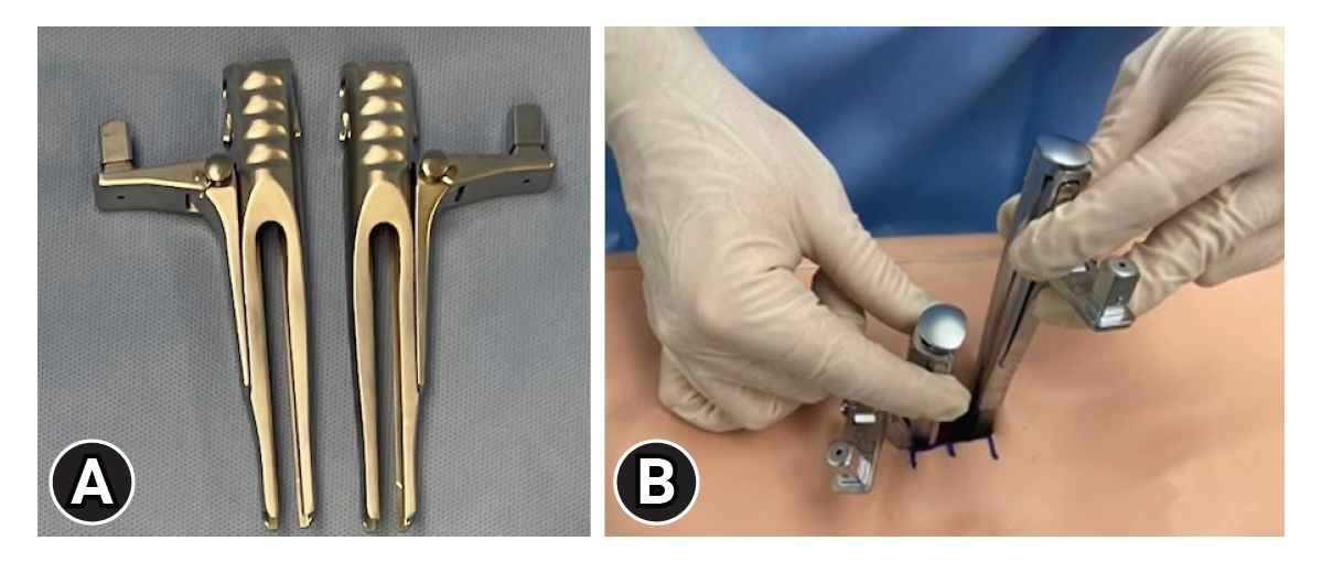
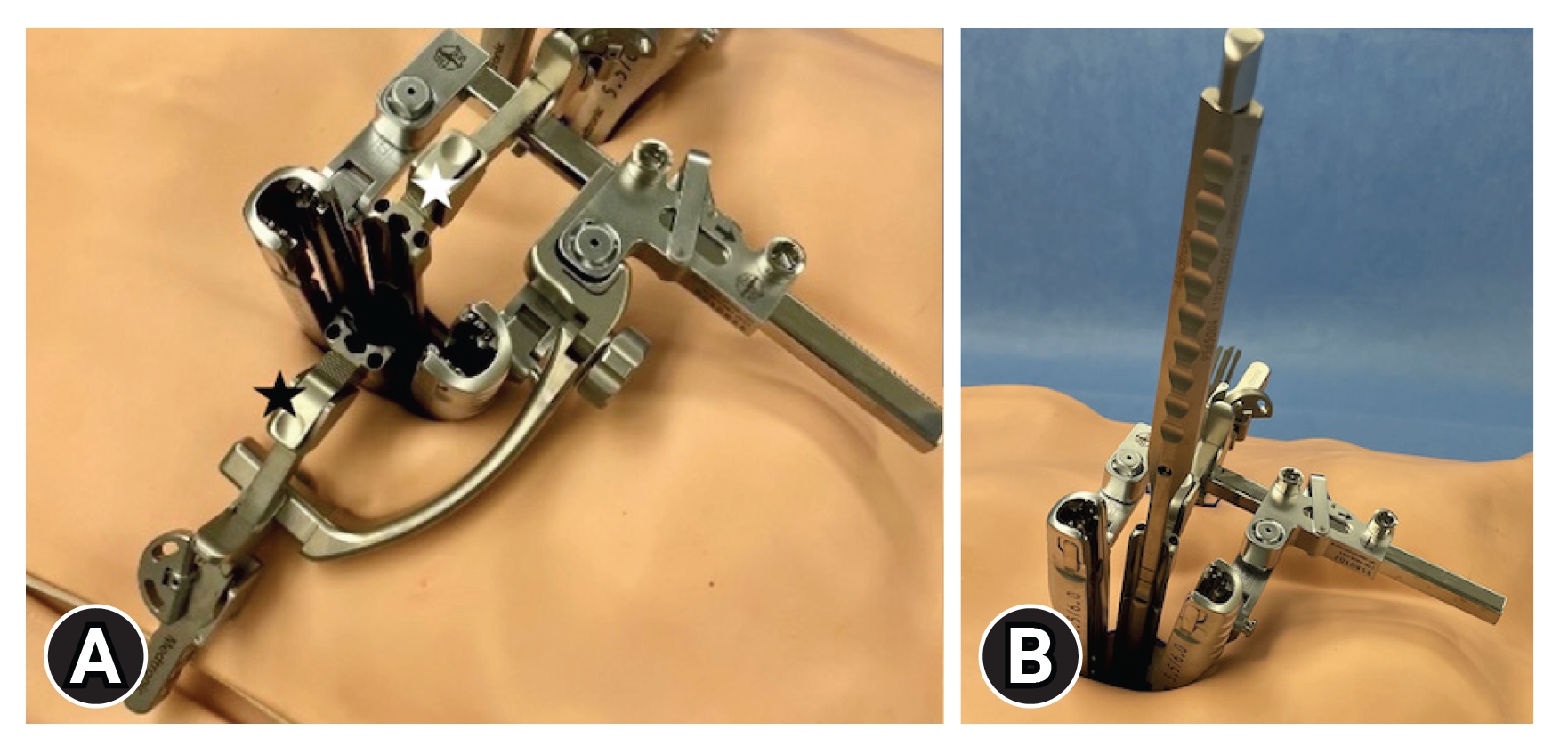
The Space-D Access System is composed of 2 sleeves (types A and B) and a distraction module. Each sleeve has a distractor arm and inner guide canula (Figure 6). After removal of the caps and properly orienting the extenders to allow for placement of the rod, the entire sleeve with the inner guide canula is placed over the extenders. From the perspective of the surgeon, type B sleeve is inserted onto the left extender and type A onto the right extender. Attachment in this manner places the distractor arms medially and creates less hindrance during subsequent steps of the procedure. Each distractor arm is then pushed downward until it engages with the pedicle screw head and the inner guides eject. This can be confirmed when the locking buttons are flush with the extenders. The inner guide cannulas are removed.
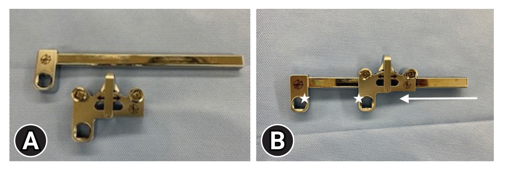
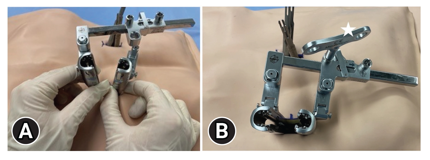
The distraction module has a distractor-pinion latch and rack (Figure 7). To assemble, the latch is placed in neutral position, and the distractor rack is then slid into it so that the connection squares are on the same side and abutting one another (Figure 7). The distractor module is then attached to the sleeves, and gentle segmental distraction can be performed with the distractor turnkey (Figure 8). This allows for opening of the foramen and posterior wall of the intravertebral disc in a superior-inferior direction.
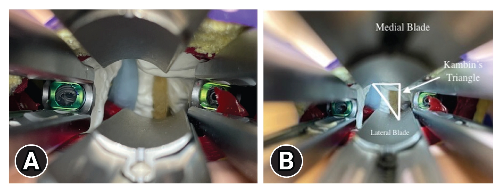
The surgical corridor leading to the disc space can be increased further by placement of medial and lateral retractor blades (Figure 9). Between the 2 retractor sleeves, the open portion of a blade holder is placed medially onto the distractor rack, and a blade is inserted. The blade manipulator can be used to extend the blade and adjust the medial-lateral angulation. A Cobb can be used to remove soft tissue off the facet joint before angulating and extending the medial blade to decrease resistance from soft tissue. For lateral tissue retraction, a lateral arm can be placed on the distractor rack followed by another blade holder and blade. Once the medial and lateral blades are in place, multiaxial screw lockers can be placed into the screw to prevent multiaxial motion.
6. Access to Disc Space and Insertion of Interbody Implant
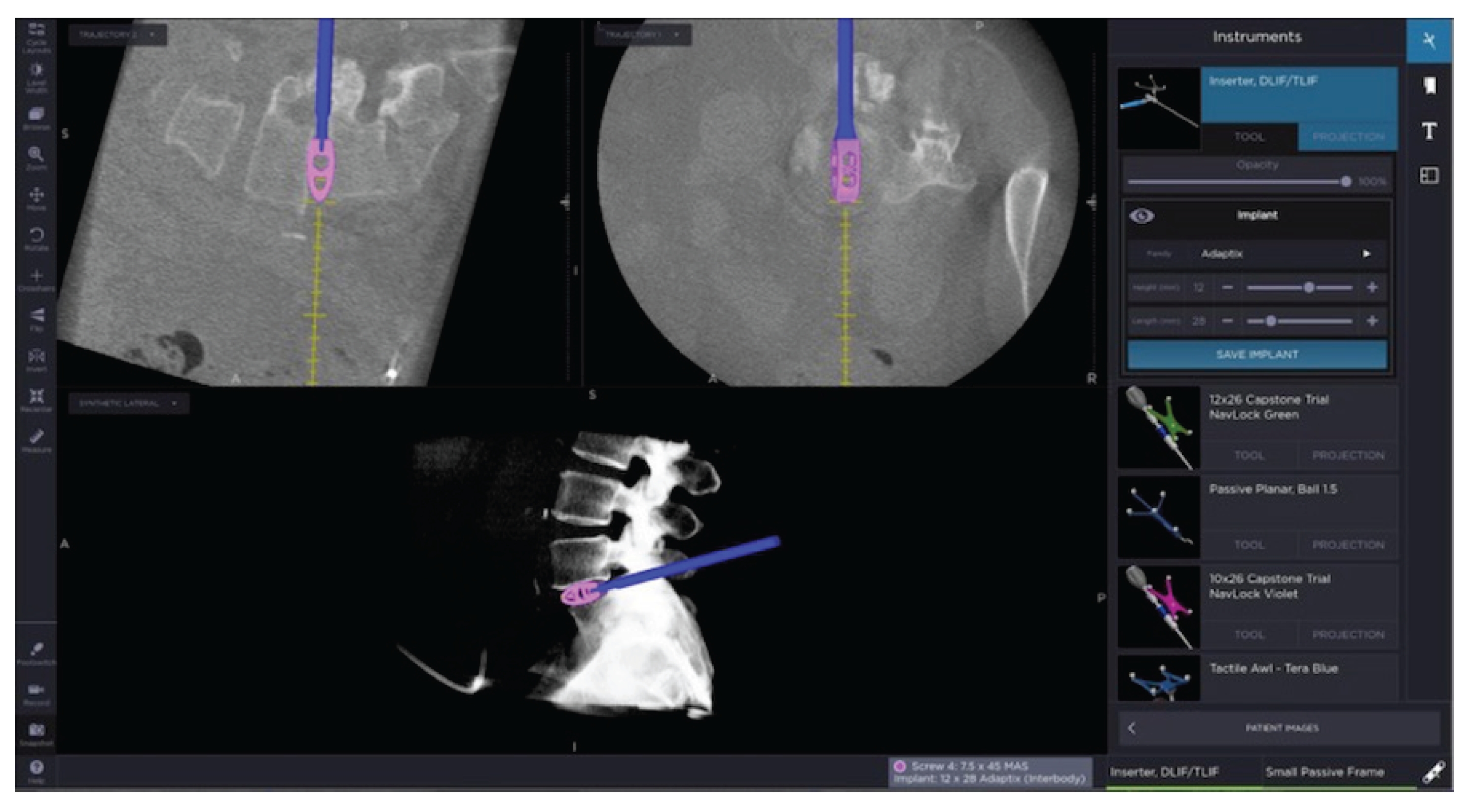
Pedicle-to-pedicle distraction with the Space-D Access System is utilized by the surgeon to gain access to the facet and disc space. Facetectomy is performed ipsilaterally or bilaterally using a drill, osteotome, and/or bone rongeurs to remove the entire superior and inferior facets. The borders of Kambin triangle are identified and the exiting nerve root is protected (Figure 10). The annulus is incised with sharp dissection, followed by removal of the disc and cartilaginous endplates with curettes and scrapers. Sequential distraction with enlarging trials is then used until the foraminal opening and original disc height are restored. In doing so, indirect decompression is achieved by allowing more space for the exiting nerve root. The interbody device is then filled with cancellous allograft and/or autograft and impacted into the disc space under direct visualization, fluoroscopy, or 3D navigation (Figure 11). If using navigation for interbody placement, only the cranial endplate is likely to shift relative to the navigation frame that is usually placed in the PSIS. It has been the experience of the senior author that the caudal endplate is still sufficiently registered to avoid gross errors in placement of the interbody device. Adequate placement of interbody is confirmed using fluoroscopy following this step.
7. Rod Placement
The Space-D Access System distraction module is set back to neutral position which releases the distractive forces and sleeves. Space-D Access System is removed to facilitate rod insertion for multisegment fixation, but is left in place for single level instrumentation. To remove, simply press on all 4 sleeve buttons to release the Space-D Access System from the pedicle extenders.
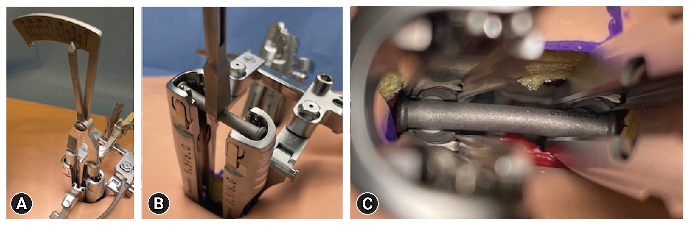
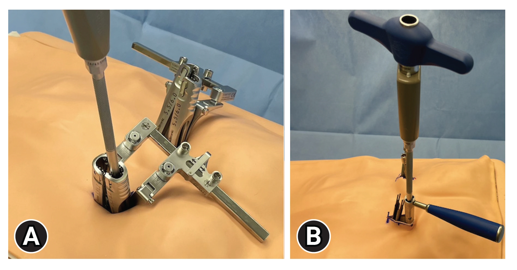
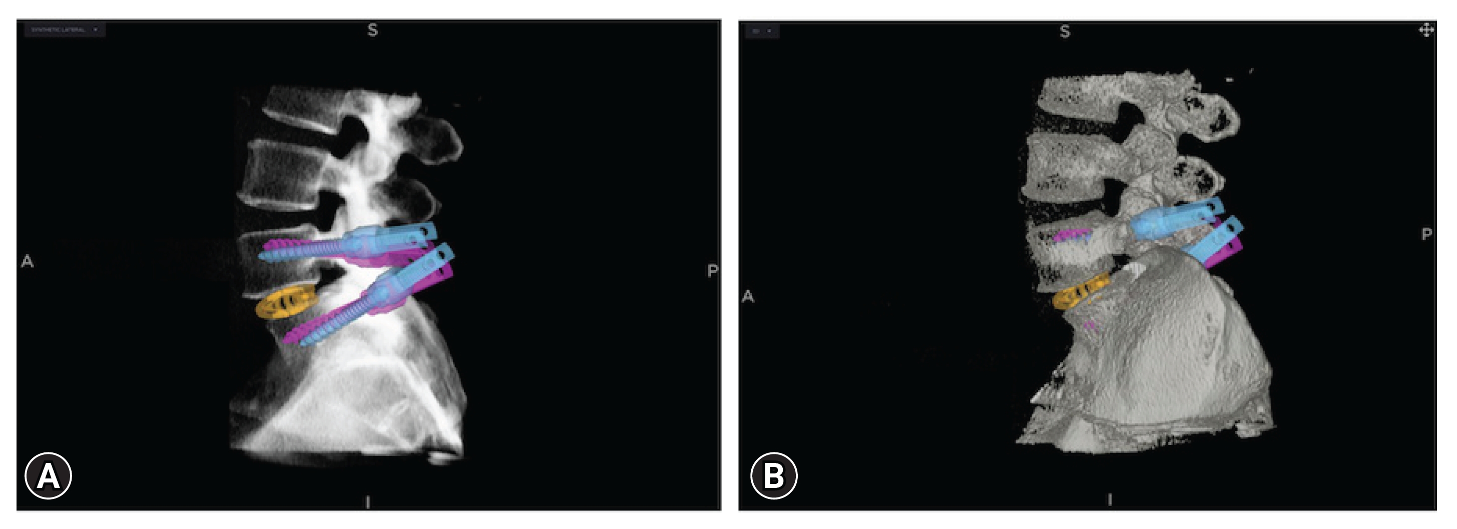
The rod template is fully seated into the most cranial and caudal screw extenders to provide the minimum rod length required for the construct (Figure 12). The slotted extenders are then aligned to allow for passage of the appropriately sized rod. The rod is attached to a percutaneous rod inserter and inserted through each of the slotted extenders (Figure 12). Next, set screws are placed into each sleeve and gently tightened atop each screw head (Figure 13). With the exception of the extenders, the Space-D Access System should be completely removed. Plain radiography in anteroposterior (AP) and lateral dimensions is obtained at this time to ensure the rod is secured to each pedicle screw and also long enough to slightly extend past the cranial and caudal limits of the construct. Final tightening of the set screws is achieved with the counter torque device to snap off each set screw cap. Lastly, a tab breaker is fitted onto each screw extender and a back-and-forth motion allows the extender to detach from the pedicle screw so it can be removed (Figure 14). Final radiographs with anteroposterior and lateral films are once again obtained to confirm appropriate placement of all hardware. With the exception of the rods, the StealthStation also has the capability to render a 3D model of the implanted hardware (Figure 15).
8. Closure
The wound is copiously irrigated and vancomycin powder is placed deep and superficial to the fascia. Final hemostasis is achieved with bipolar coagulation. The fascial layer and dermis are closed with Vicryl sutures and skin with Monocryl sutures. Local anesthesia is infiltrated into the wound, and the patient is awakened from anesthesia.
RESULTS/DISCUSSION
The goal of lumbar fusion is to achieve adequate neurological decompression (spinal canal and/or neural foramina), restore physiologic spinal alignment, and prevent abnormal motion. While the indications for an open TLIF and MIS TLIF are relatively similar, there are certain scenarios in which one method may be preferred. In our senior author’s experience, pathologies that require an extensive decompression such as high-grade spondylolisthesis favor an open TLIF. On the other hand, MIS TLIF may be preferred for patients with foraminal stenosis, recurrent disc herniations and other degenerative pathology. Other common indications for TLIF for which an open and MIS approach are equally preferred is low-grade spondylolisthesis, postlaminectomy instability, and pseudoarthrosis [12].
CONCLUSION
The Space-D Access System is the only multifunctional device that allows tissue retraction and pedicle-to-pedicle distraction or compression while performing a MIS TLIF. To our knowledge, this is the first paper to describe the device and its use for MIS TLIF with written instructions and visuals using an anatomic model.