INTRODUCTION
Posterior lumbo-pelvic instrumentation is used to treat spinal instability caused by a spectrum of lumbosacral or sacral pathologies. The objective is to provide segmental stabilization and superior biomechanical stability across the lumbosacral junction and to prevent failure of long segment constructs. Lumbo-pelvic fixation involves the insertion of the iliac screws which can be either a conventional iliac screw or S2 alar-iliac (S2AI) screw [1].
The conventional open iliac screw requires extensive exposure of the posterior portion of the iliac crest and dorsal surface of sacrum up to S2 body and proximal extent depending upon the length of the construct. This exposure requires subperiosteal stripping at the origin of gluteus maximus at posterior superior iliac spine (PSIS), attachments of erector spinae, and multifidus at the medial and lateral surface of the posterior part of the sacrum for anatomically orientation, screw entry point, trajectory guidance and to accommodate rod and lateral connectors.
This extensive exposure damages the dorsal sacroiliac, iliolumbar and sacrotuberous ligaments losing their primary restraints function. Disruption of these muscles and ligaments in open technique will lead to soft issue devascularization leading to wound healing problems, deep hematoma formation, and requiring early secondary surgical procedures in 26% of the patients for wound-related complications [2-4].
Minimal invasive (MI) techniques can overcome the disadvantages of traditional open techniques with better biomechanical stability rates and clinical results. MI approach follows the principles of percutaneous pedicle screw insertion and offers several advantages such as minimizing blood loss and tissue trauma-minimizing paraspinal muscle injury, preserving the attachments to the sacrum and posterior superior iliac spine, lesser infection rates, and faster recovery than the standard open techniques [5]. The intraoperative image guidance assists the surgeons to determine the ideal entry point of the screw and screw trajectory [6,7] in real-time reducing the radiation exposure.
Iliac screws can be inserted either in a conventional open method or by MI technique which can be either navigated (2D/3D) or non-navigated. The non-navigated freehand technique involves screw placement relying on anatomical landmarks minimizing extensive exposure of the ilium to access the entry point and does not require extensive intraoperative fluoroscopy for screw trajectory guidance. On the other hand, navigated iliac screw insertions are entirely image-dependent.
This article describes the least invasive techniques of iliac screw insertion which can add to the surgeon’s armamentarium for a better outcome.
MATERIALS AND METHODS
A consecutive series of seven patients were treated with lumbo-pelvic instrumentation for various diseases of the lumbosacral junction. All patients had significant back pain and or leg pain affecting their daily activities. All patients underwent MI insertion of iliac screw bilaterally using navigation guidance (2D/3D) (n=5) or using the free hand-guided technique (n=2). Patients with underlying spondylodiscitis (n=4), osteoporosis (n=2) received antibiotics, antitubercular therapy, and osteoporosis treatment respectively. Post-operative outcome was assessed with respect to post-operative ambulatory status, status of primary disease, wound and implant related complication at last follow up.
1. Description of Technique
1) Freehand Non-Navigated-Guided Iliac Screw Insertion
The patient is positioned prone on the operative table. The required area is scrubbed and draped maintaining sterile precautions. A 2–3 cm vertical skin incision is made approximately 2 cm medial to PSIS on either side of the midline, using AP (Anterior-posterior) fluoroscopy. Pre-operative assessment of the iliac slope and direction can guide us towards choosing our skin incision. In cases with a wide pelvis, the angulation for the screw may be higher and skin incisions converge more towards the midline, whereas in patients with a narrow pelvis, the iliac wings are more straighter and the screw angulation will be less angulated, placing the skin incisions relatively farther away from the midline. Sharp dissection is carried down towards the PSIS and the fascia over PSIS is split along the entire length of the incision. It is important to correctly orient the direction in which dissection is being to expose the PSIS. After exposure of PSIS, a bony prominence can be palpated at the inferior portion of PSIS and the entry point is 1 cm cranial and medial to that point. Choosing this entry point is important as the ridge of PSIS buries the screw head avoiding screw head prominence. The entry point is again confirmed with an AP fluoroscopic image. Once the entry point is chosen, a cortical window is made using a high-speed drill.
Using a blunt curved pedicle gear shift probe at the entry point directed towards the anterior inferior iliac spine (AIIS) (Figure 1A), the probe is initially aimed laterally avoiding entry into the sacroiliac joint and rotated medially after a length of 2 cm advancing towards AIIS. As the blunt tip of the instrument encounters the dense cortical bone, the probe needs to rotated 180 degree, thus guiding between the inner and outer iliac tables via tactile feedback maintaining trajectory cephalad to sciatic notch and acetabulum with intermittent AP fluoroscopy (Figure 1B). The screw path is palpated with a ball tip probe to check for cortical breach in the walls of the ilium. If there is doubt of cortical breach, teardrop view after placing a probe can be used to confirm appropriateness on intraosseous screw path. Dilatation is carried out in standard fashion and an iliac screw of appropriate length and diameter is inserted after tapping along the screw trajectory (Figure 1C) and screws are interconnected with the rod.
2) Image-Guided Navigated Iliac Screw Insertion
The patient is positioned prone on allen table and draping of the patient is performed as illustrated before. PSIS is palpated and the reference frame for navigation is inserted either on the right or left side at the superior lateral margin of PSIS via stab incision. The frame is angled slightly caudally to have an unobscured working field and is important to remain at a fixed position throughout the procedure which is essential for the accuracy of navigation. Next is the image acquisition phase during which the O arm (O-arm® O2 Imaging System, Medtronic, 300 Foster St, Littleton, MA 01460, United States) is centred over the lumbosacral junction and spin is performed after confirming the required extent on AP and lateral images. On completion, image data is transferred to the navigation system.
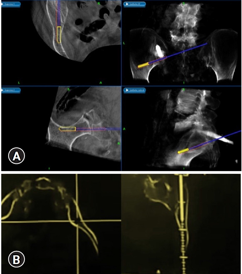
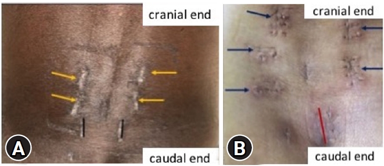
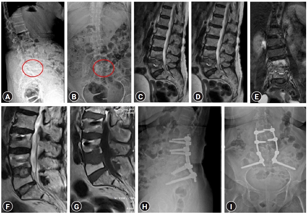
There are many techniques and entry points for iliac screw insertion. Choosing an optimal screw entry point is based on the patient’s anatomy and required trajectory which is aimed towards AIIS above the greater sciatic notch not penetrating the sacroiliac joint. With the help of a navigable probe, the skin incision is planned after visualizing the intended trajectory on the navigation screen (Figure 2A) and entry points are marked. 1.5 cm vertical incision, either a paramedian incision on both sides (Figure 3A) or a midline (Figure 3B) incision is made based on the entry points chosen under navigation guidance. Skin, subcutaneous tissue, and fascia are incised without the need for any subperiosteal dissection and without disrupting the muscular and ligamentous attachments. After choosing the optimal trajectory a navigable jamshidi needle is docked at the starting point and is advanced simultaneously allowing for real-time multiplanar images on the navigation screen (Figure 2B). Once the jamshidi crosses around 50 mm to 60 mm in length, the guidewire (K wire) is inserted internally and the jamshidi needle is removed. Cannulated cancellous screw tap is threaded over the guidewire and is tapped along the trajectory of the screw and ideal screw length is measured on the navigation screen. Iliac screw of adequate length and diameter is inserted under navigation guidance and similar steps are performed on the opposite side. Pedicle screws are cannulated proximally across the lumbar spine in a standard percutaneous fashion. The entire construct is interconnected with the rod after contouring it in the coronal and sagittal plane (two planes) and is passed in sub facial plane from the cephalad to the caudal direction. Wounds are closed in a subcuticular fashion (Case examples; Figure 4–6). Case example 1, 77-year-old female who presented with low back pain affecting her daily activities, examination revealed no deficits. X ray of lumbar spine revealed collapse of L5 vertebral body with endplate destruction at L4 (Figure 4A B). MRI showed L5 vertebral body collapse with altered signal intensity with spondylodiscitis at L4-L5 with enhancing prevertebral soft tissue component causing nerve root compression (Figure 4C–E). Patient was planned for L3 – pelvis stabilization, decompression at L4-L5 with biopsy. Histopathology report was suggestive of tubercular spondylodiscitis and antitubercular therapy was initiated. Follow up MRI and X ray at 1 year revealed disease resolution with symptomatic improvement (Figure 4F–I).
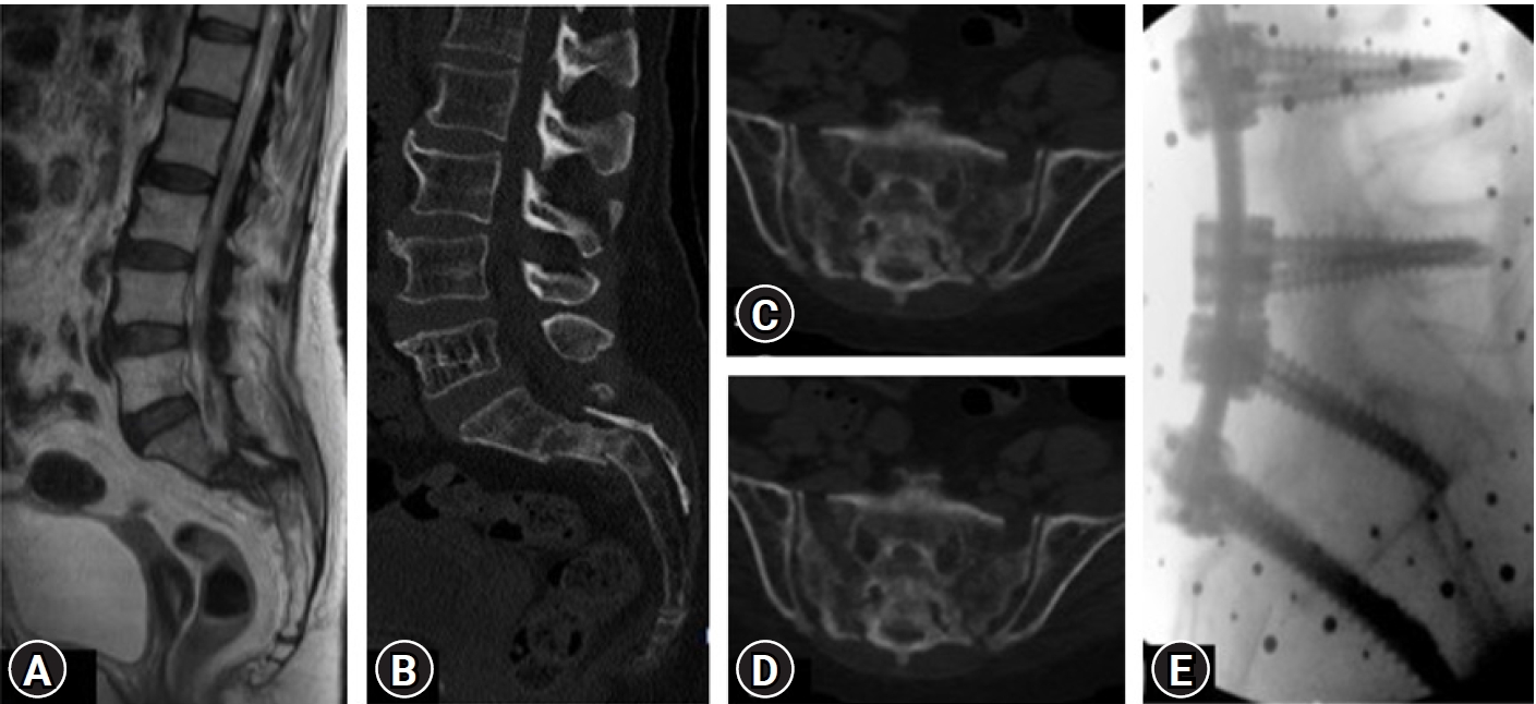
Case example 2, 69-year-old female, known case of rheumatoid arthritis presented with severe low back pain, inability to stand and walk, normal neurology on examination. Imaging revealed zone 1 sacral insufficiency with displacement (Figure 5A–D) with T score of –3.3 on DEXA scan. Patient underwent MI pedicle and iliac screw fixation (L3-pelvis) and was mobilized on day 1 with good reduction in her back pain. Immediate postoperative X-ray showing lumbopelvic construct from L3 to the pelvis (Figure 5E).
Case example 3, a 50-year-old male presented with low back pain, bilateral lower limb radiculopathy, and difficulty in walking. Imaging and biopsy at L4-L5, was suggestive of bacterial spondylodiscitis. Because of his worsening clinical condition, repeat imaging was performed revealed progression of disease with L5-S1 endplate irregularity, enhancing intervertebral disc and epidural collection causing neural compression (Figure 6A–D). Patient underwent MI L5-S1 transforaminal interbody fusion, pedicle, and iliac screw placement. Postoperatively, patient had good reduction of radicular and back pain with the resolution of disease in follow up period (Figure 6E–H).
RESULTS
A total of 7 patients (5 women and 2 men) underwent percutaneous iliac screw (PIS) fixation (5 navigated and 2 non navigated- freehand) for various pathological conditions of the lumbosacral spine. Two patients had interbody cages with allografts within and around them placed at the L5-S1 level. The majority of the cases (n=4) were spondylodiscitis. All patients underwent successful PIS fixation, with no intraoperative and immediate postoperative complications. No patients required conversion to open procedure and all patients were mobilized on postoperative day 1 with significant relief in pre-operative back pain. None of the patients had wound or hardware related complications till the last follow-up. However, one patient of L5-S1 tubercular spondylodiscitis succumbed three months post-surgery due to a cause unrelated to surgery but due to pre-existing chronic kidney disease (Table 1).
DISCUSSION
The objective of the lumbo-pelvic construct is to produce triangulation effect, reducing screw pull-out, torsional stability [8], reducing stress on S1 screw, and provide adequate stabilization.
Although there are several methods for pelvic fixation which have been described, iliac screws offer superior biomechanical stability as it involvesplacing the screw in zone III-both iliac wings (O’Brien et al. classification) making the construct biomechanically superior as the screw is inserted anterior to the lumbosacral pivot point in sagittal and lateral to it in coronal plane acting as stable distal anchors [9].
Conventional open iliac screw fixation has been the standard of treatment for various conditions requiring lumbo-pelvic fixation, but owing to its potential complication there is an increasing trend towards adapting MI technique of iliac screw insertion. MI placement of iliac screws requires accurate pre-operative strategy in terms of incision planning and placement, desired screw trajectory, appropriate rod contouring, and optimal screw characteristic in terms of screw diameter and length.
In MI insertion a midline incision can be planned based on navigation and in a non-navigated freehand technique, an incision can be placed medial to PSIS. The advantage with the midline incision is, there would be roughly 1.5–2 cm depth at which screw head is placed and soft tissue acts as an envelope covering the screw head and avoiding screw head prominence especially in thin individuals. The other advantage of a single midline incision is it would reduce the total number of incisions.
About trajectory planning, two trajectories are available for iliac screw placement, the first one is guided towards the superior rim of the acetabulum, and the second one directs to AIIS [10], with entry points starting at the PSIS. The trajectory towards AIIS offers a longer screw and avoids the risk of acetabular violation [11]. Irrespective of the technique and image assistance used the ideal trajectory would aim to direct screw towards AIIS above 1–2 cm of the sciatic notch, above the acetabulum with 20–45 degrees caudal inclination and lateral inclination of around 30–45 degrees.
Imaging is the key to safe screw placement, with intraoperative O arm and navigation multiplanar real-time images are obtained on the screen which facilitates choosing the right screw entry point, desired trajectory, and right screw length and diameter. On the other hand, freehand techniques are based on anatomical points.
The freehand technique as described by Fridley et al. [12] uses the superior edge of the lamina and spinous process of L5 as anatomical landmarks. The shafts of the pedicle probe should be parallel to the L5 lamina and the shaft of the pedicle probe of both sides should intersect each other at the L5 spinous process. If the screw follows the correct path, the path of the probe never goes over the L5-S1 facet joint on the AP fluoroscopy view, and also AP view will assist in preventing sciatic notch violations.
Intraoperative fluoroscopy is of absolute necessity, there are numerous fluoroscopic views and true lateral view in which sciatic notches are superimposed is the primary view for screw insertion. The teardrop view will help in inserting a screw in the widest part ilium which is the centre part on the teardrop view and the screw should be confined within the bony margins of the teardrop on the obturator outlet view. The others additional views which can be used are the obturator inlet view and iliac oblique view. Screw characteristics are of paramount importance, the most commonly used iliac screws are 7.5 cm in diameter and length of 60–80 mm [13,14]. In our series, all screws were more than 6.5 mm in diameter and 60 mm in length with the largest measuring 7 mm in diameter and 70 mm in length. Another technical difficultly is rod contouring and connecting to the proximal construct which needs special attention, rod is always fashioned in two planes – coronal and sagittal. The rod has to be contoured to have a hyperacute lordotic bend of around 30 degrees in the distal-most segment of the rod to facilitate easier connection and the rod has to be always passed from cephalad to caudal. The presence of S1 screw necessitates contouring of a shorter segment of the rod to link S1 and iliac screw head. In indicated cases, it is always preferable to have anterior support especially those constructs extending into the dorsal spine. The use of an interbody cage in anterior reconstruction will not only remove stress on posterior instruments but also promotes fusion. The objective of any lumbo-pelvic construct is to prevent failure and increase the stability of construct, whether a single or dual iliac screw (DIS) is adequate depends on clinical situations. DIS when compared with a single iliac screw, DIS is optimum in terms of stability at the caudal part of the spinopelvic construct and offers higher construct stiffness with respect to compression and torsion. DIS can also be performed by MIS fashion which is described by Hasan and Liu [15].
Use of O arm and navigation renders 3D visualization of bony structures, helps in planning the desired trajectory and guiding the screw with real-time multiplanar images eliminating fluoroscopic exposure and determine the suitable entry point of the screw, screw trajectory [7,13] and maximizing screw length and diameter. Utilizing a submuscular or MI approach to the PSIS and sacrum may reduce soft tissue complications avoiding disruption of erector spinae muscle, posterior sacroiliac, and interosseous iliac ligament contributing to lower infection rates and more rapid recovery than the standard open techniques.
Emami et al. [13] and Tsuchiya et al. [14] group reported various wound and hardware-related complications following the open screw technique. Though there are direct no comparative data between open and percutaneous techniques to assess hardware and wound complications, Liu et al. [16] and Wang et al. [17] group reported no wound or hardware related complications in their case series of PIS insertion.
Liu et al. [16] and Wang et al. [17] group performed PIS insertion in 5 and 24 patients respectively using intraoperative fluoroscopy as a key primary tool for image guidance and screw insertion with the removal of cortical bone to accommodate the screw head [17]. In contrast, our technique of freehand MIS iliac screw placement is based on anatomical landmarks which reduce the overall time of radiation exposure with minimal insult to supporting structure of ilium and PSIS and use of navigation would facilitate in planning appropriate and accurate entry points, trajectory, and screw insertion.
Wound closure should always be in a layered fashion and all efforts should be made to close the fascia to avoid hardware prominence especially in the paramedian incision. Ultimately, larger clinical series is required to demonstrate the safety of this technique.
CONCLUSION
Lumbo-pelvic instrumentation technique has been redefined over the decade. Percutaneous insertion of the iliac screw can safely be performed without bony violation along screw trajectory with limited soft tissue damage offering the same biomechanical stability and overcoming the disadvantages of open iliac screw insertion.


